Projekt 1: Schallgeschwindigkeit
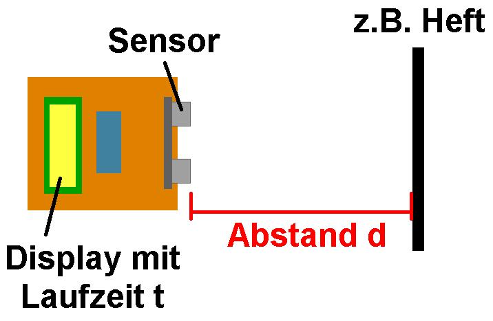
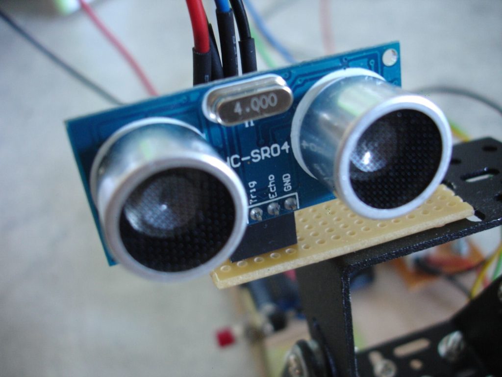
Mit dem bekannten Ultraschallmodul HC-SR04 kann man etwa die Distanz von Objekten bestimmen. Hierfür wandelt das Modul die gemessene Laufzeit t mittels „bekannter“ Schallgeschwindigkeit c in Luft (rund 340 m/s) in eine Distanz d = c · t/2 um.
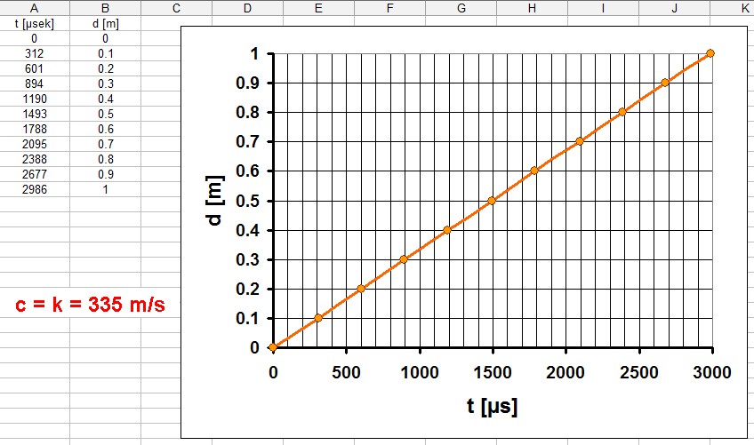
Man kann sich aber auch umgekehrt für einen bestimmten Abstand d nur die Laufzeit t anzeigen lassen und daraus mittels c = d / (t/2) die jeweilige Schallgeschwindigkeit berechnen.
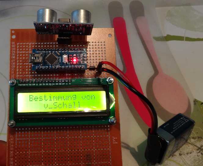
Für dieses Projekt benötigt man wie so oft nur einen Arduino, ein 16 x 2 I2C display und eben den HC-SR04 Sensor. Dies kostet aus Fernost zusammen nur um die 10 Euro.


Arduino-Code:
// Programm zur Bestimmung der Schallgeschwindigkeit
// =================================================

// Gemessen wird die Laufzeit des Ultraschalls vom Sender zum Objekt und wieder zurück zum Empfänger
// -------------------------------------------------------------------------------------------------

#include <LiquidCrystal_I2C.h>
#include <Wire.h>

LiquidCrystal_I2C lcd(0x27,16,2);  // set the LCD address to 0x27 for a 16 chars and 2 line display. ACHTUNG: Adresse kann auch 0x3F sein !!!

// Anschlüsse:
// GND - GND
// VCC - 5V
// SDA - ANALOG Pin 4
// SCL - ANALOG pin 5


int trigPin = 3; // set pin 3 as trig pin
int echoPin = 4; // set pin 2 as echo pin
int time;


// =========================
// ======== SEETUP =========
// =========================

void setup()
   {
    Serial.begin(9600);

    pinMode(trigPin, OUTPUT);  // set trig pin as output, we send pulse through this
    pinMode(echoPin,INPUT);    // set echo pin as input, we detect echo through this pin

    lcd.init();                // initialize the lcd
    lcd.backlight();
    lcd.setCursor(1,0);
    lcd.print("Bestimmung von");
    lcd.setCursor(4,1);
    lcd.print("v_Schall");

    delay(3000);

    lcd.setCursor(0,0);
    lcd.print("t =           ");
    lcd.setCursor(4,1);
    lcd.print("         ");
   }


// ================================
// ======== HAUPTSCHLEIFE =========
// ================================

void loop()
   {
    //sending 10 microsecond width pulses, frequency ~ 40KHz

    digitalWrite(trigPin, LOW);
    delayMicroseconds(2000);

    digitalWrite(trigPin,HIGH);      // trig pin
    delayMicroseconds(10);           // pulse width 10 microseconds
    digitalWrite(trigPin, LOW);      // trig pin off

    time = pulseIn(echoPin, HIGH);   // pulseIn(), function return time in microseconds

    //print time on the serial monitor

    Serial.print(" Time taken for the pulse to travel:  ");
    Serial.print(time);
    Serial.println(" microseconds");

    lcd.setCursor(4,0);
    lcd.print("            ");
    lcd.setCursor(4,0);
    lcd.print(time/2);
    lcd.print(" us");

    delay(400);
   }
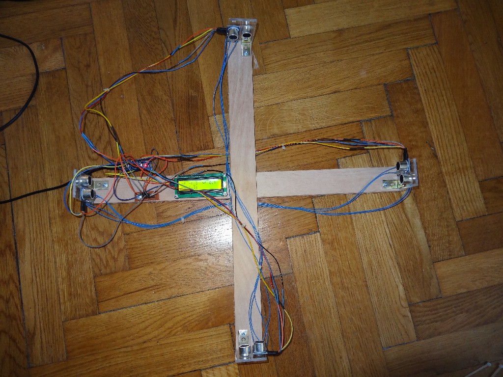
Projekt 2: Ultraschallanemometer
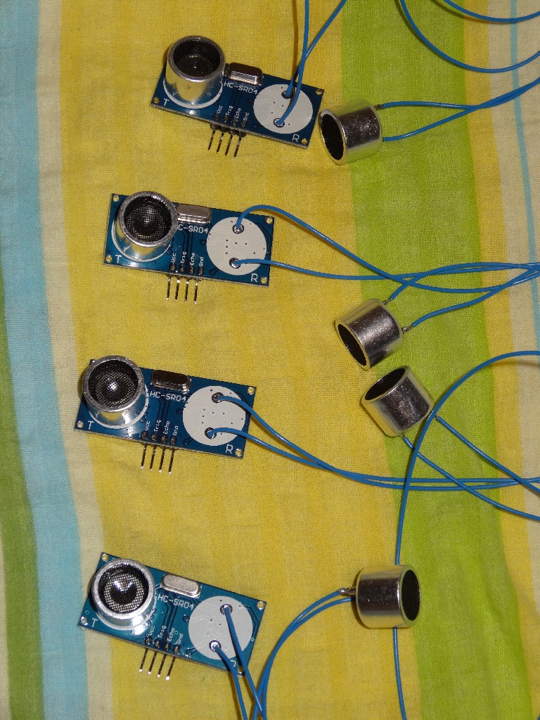
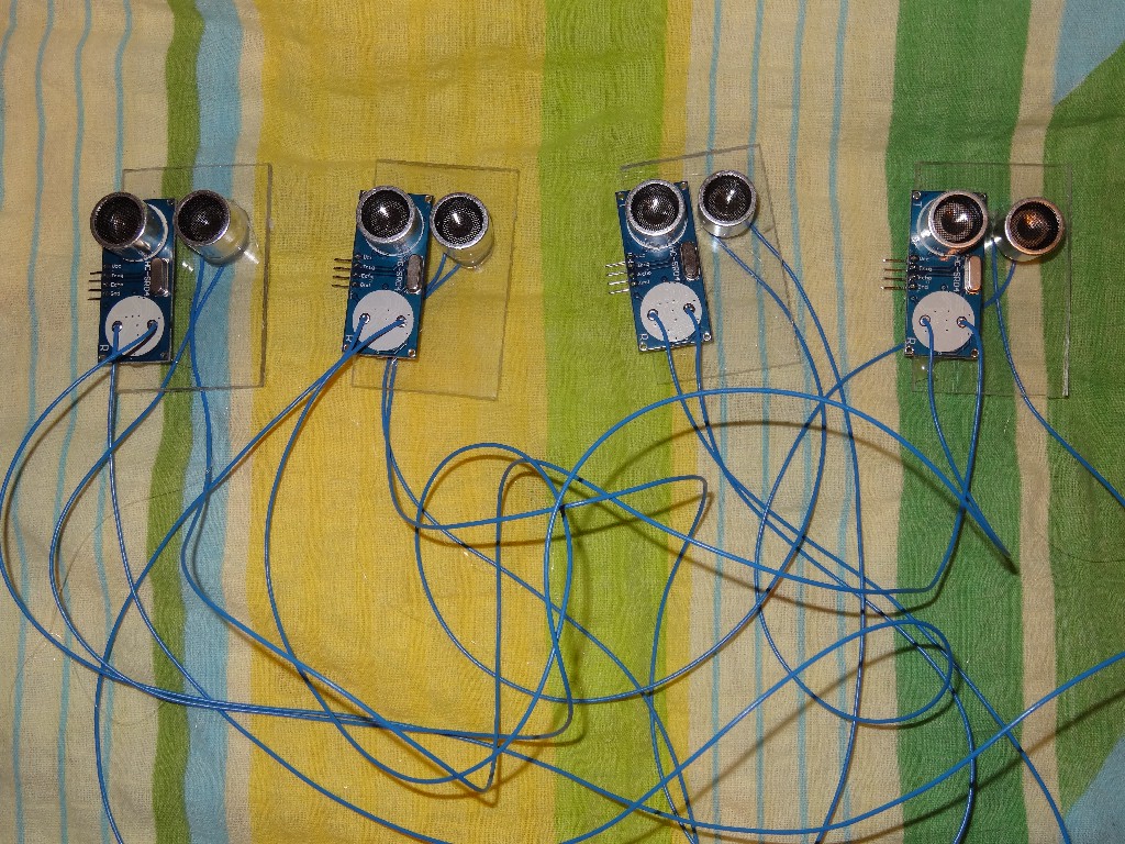
Mit einem Anemometer bestimmt man die Windgeschwindigkeit. Üblicherweise kommt hier ein Schaufelrad zum Einsatz, welches sich bei einer bestimmten Windgeschwindigkeit mit einer bestimmten Winkelgeschwindigkeit dreht. Man kann ein Anemometer aber auch mit dem Ultraschallmodul HC-SR04 umsetzen. Konkret benötigt man 4 Stück davon. Man muss zuerst von allen Modulen z.B. den Empfänger ablöten. Danach bastelt man aus Holz ein Kreuz. An den 4 Enden des Kreuzes kommt nun je ein Sender. Den jeweiligen Empfänger postiert man genau gegenüber.
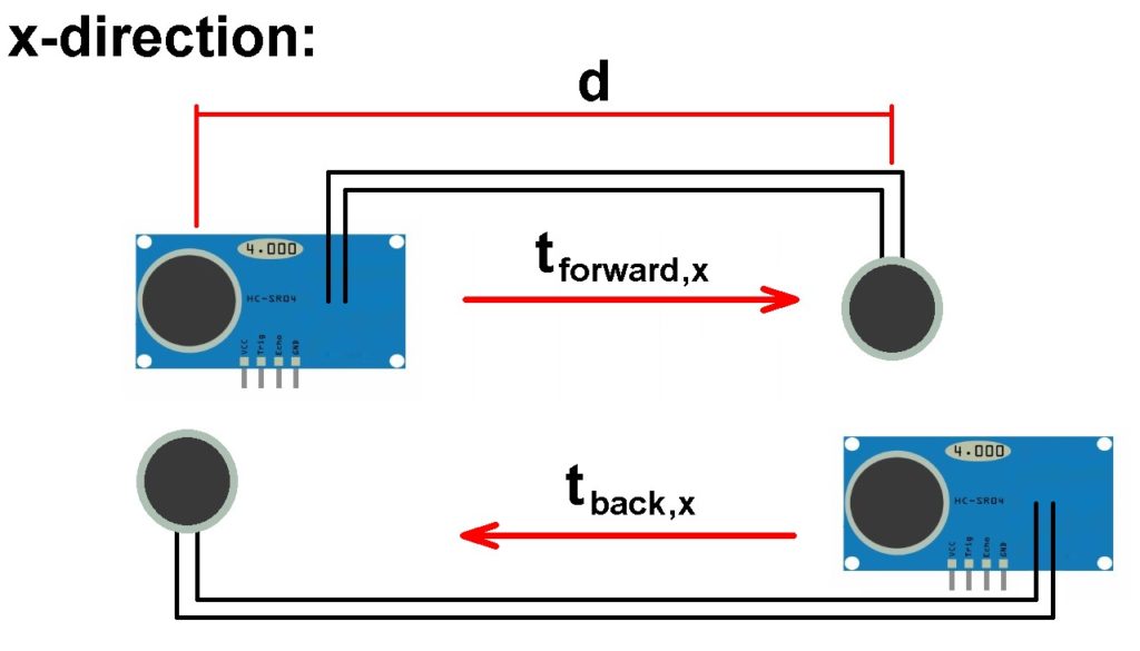
Wie kann man nun daraus die Windgeschwindigkeit v berechnen. Nun man bestimmt hintereinander die Laufzeit für alle 4 Strecken (je zwei davon unterscheiden sich nur bzgl. ihrer Richtung). Die Schallgeschwindigkeit c überlagert sich mit der Windgeschwindigkeit v. Es gilt dabei etwa für die x-Richtung:
Geschwindigkeit 1: vx,ges 1 = vx + cx
Geschwindigkeit 2: vx,ges 2 = –vx + cx
Ermittels werden jeweils die beiden Laufzeiten t1 und t2.
Diese hängen mit den Geschwindigkeiten vx,ges wiefolgt zusammen:
vx,ges 1 = d / t1
vx,ges 2 = d / t2
Dies liefert ein Gleichungssystem (2 Glg. mit 2 Unbekannten). Eliminiert man daraus cx, erhält man für die Windgeschwindigkeit vx in x-Richtung:
vx = (d/2) · [(1/t1) – (1/t2)]
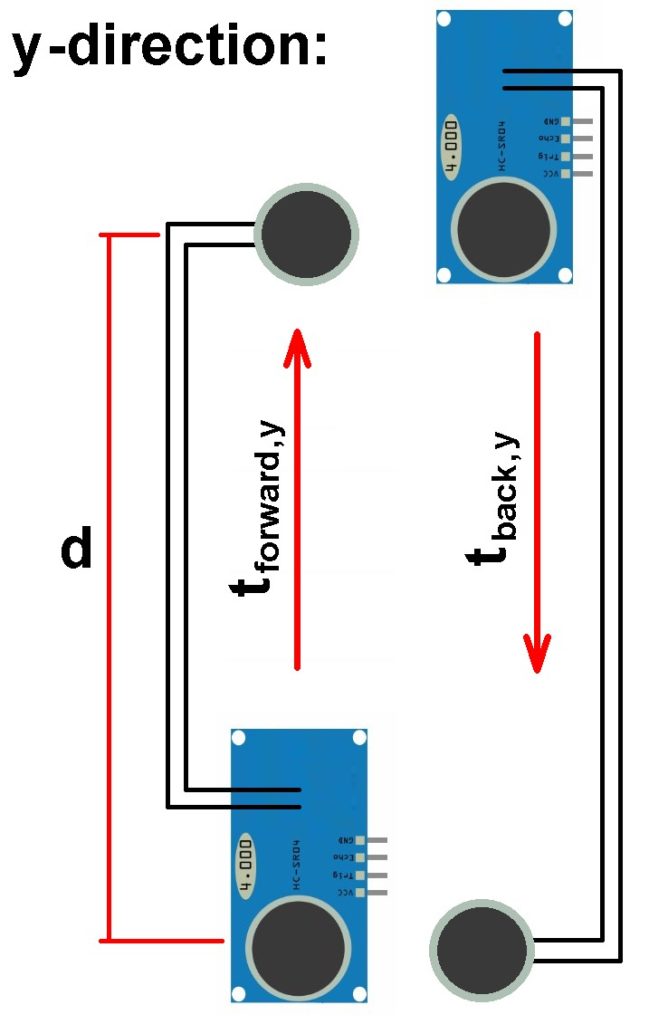
Analog dazu lässt sich die Windgeschwindigkeit in y-Richtung bestimmen. Mittels Pythagoras erhält man schlussendlich die Windgeschwindigkeit
v = √(vx² + vy²).
Zusätzlich kennt man durch die Einzelkomponenten vx bzw. vy die Richtung des Winds.


Arduino-Code:
// Programm zur Bestimmung der Schallgeschwindigkeit
// =================================================
// Gemessen wird die Laufzeit des Ultraschalls vom Sender zum Objekt und wieder zurück zum Empfänger
// -------------------------------------------------------------------------------------------------
#include <LiquidCrystal_I2C.h>
#include <Wire.h>
LiquidCrystal_I2C lcd(0x3F,16,2); // set the LCD address to 0x27 for a 16 chars and 2 line display. ACHTUNG: Adresse kann auch 0x3F sein !!!
// Anschlüsse:
// GND - GND
// VCC - 5V
// SDA - ANALOG Pin 4
// SCL - ANALOG pin 5
int VoutPin_x_f = 2; // Vout pin for sensor x_forward
int trigPin_x_f = 3; // set pin 3 as trig pin for sensor x_forward
int echoPin_x_f = 4; // set pin 4 as echo pin for sensor x_forward
int VoutPin_x_b = 5; // Vout pin for sensor x_back
int trigPin_x_b = 6; // set pin 6 as trig pin for sensor x_back
int echoPin_x_b = 7; // set pin 7 as echo pin for sensor x_back
int VoutPin_y_f = 8; // Vout pin for sensor y_forward
int trigPin_y_f = 9; // set pin 9 as trig pin for sensor y_forward
int echoPin_y_f = 10; // set pin 10 as echo pin for sensor y_forward
int VoutPin_y_b = 11; // Vout pin for sensor y_back
int trigPin_y_b = 12; // set pin 12 as trig pin for sensor y_back
int echoPin_y_b = 13; // set pin 13 as echo pin for sensor y_back
float time_x_f, time_x_b, time_y_f, time_y_b; // measured time forward and back in x- and y-direction
float time_x_offset_b, time_y_offset_f; // offset-values for x- and y-direction because of different sensor-positions
float v_x, v_y, v_total; // velocities in x-, y-direction
float distance_x, distance_y; // distance between the receiver and transducer in x- and y-direction
// =========================
// ======== SEETUP =========
// =========================
void setup()
{
Serial.begin(9600);
pinMode(VoutPin_x_f, OUTPUT); // set Vout pin as output
pinMode(trigPin_x_f, OUTPUT); // set trig pin as output, we send pulse through this
pinMode(echoPin_x_f,INPUT); // set echo pin as input, we detect echo through this pin
pinMode(VoutPin_x_b, OUTPUT); // set Vout pin as output
pinMode(trigPin_x_b, OUTPUT); // set trig pin as output, we send pulse through this
pinMode(echoPin_x_b,INPUT); // set echo pin as input, we detect echo through this pin
pinMode(VoutPin_y_f, OUTPUT); // set Vout pin as output
pinMode(trigPin_y_f, OUTPUT); // set trig pin as output, we send pulse through this
pinMode(echoPin_y_f,INPUT); // set echo pin as input, we detect echo through this pin
pinMode(VoutPin_y_b, OUTPUT); // set Vout pin as output
pinMode(trigPin_y_b, OUTPUT); // set trig pin as output, we send pulse through this
pinMode(echoPin_y_b,INPUT); // set echo pin as input, we detect echo through this pin
lcd.init();
lcd.backlight();
lcd.setCursor(1,0);
lcd.print("Ultraschall");
lcd.setCursor(4,1);
lcd.print("Anemometer");
delay(3000);
lcd.setCursor(1,0);
lcd.print(" ");
lcd.setCursor(4,1);
lcd.print(" ");
lcd.setCursor(0,0);
lcd.print("x");
lcd.setCursor(8,0);
lcd.print("y");
lcd.setCursor(0,1);
lcd.print("v:");
distance_x = 0.47;
distance_y = 0.47;
time_x_offset_b = 1325.50 - 1307.77; // offsetvalues calculated with the average of 10000 values in both x-directions
time_y_offset_f = 1324.54 - 1321.11; // offsetvalues calculated with the average of 10000 values in both y-directions
}
// ================================
// ======== HAUPTSCHLEIFE =========
// ================================
void loop()
{
// measuring the velocity forward in x-direction
// =============================================
time_x_f = 0.0;
digitalWrite(VoutPin_x_f, HIGH);
delay(220);
for(int i = 0; i < 100; i++)
{
digitalWrite(trigPin_x_f, LOW);
delayMicroseconds(2000);
digitalWrite(trigPin_x_f,HIGH);
delayMicroseconds(10);
digitalWrite(trigPin_x_f, LOW);
time_x_f = time_x_f + 1.0 * pulseIn(echoPin_x_f, HIGH); // pulseIn(), function return time in microseconds
}
digitalWrite(VoutPin_x_f, LOW);
time_x_f = time_x_f / 100.0;
Serial.print("t_x_f = ");
Serial.println(time_x_f,2);
// measuring the velocity back in x-direction
// ==========================================
time_x_b = 0.0;
digitalWrite(VoutPin_x_b, HIGH);
delay(220);
for(int i = 0; i < 100; i++)
{
digitalWrite(trigPin_x_b, LOW);
delayMicroseconds(2000);
digitalWrite(trigPin_x_b,HIGH);
delayMicroseconds(10);
digitalWrite(trigPin_x_b, LOW);
time_x_b = time_x_b + 1.0 * pulseIn(echoPin_x_b, HIGH); // pulseIn(), function return time in microseconds
}
digitalWrite(VoutPin_x_b, LOW);
time_x_b = (time_x_b / 100.0) + time_x_offset_b;
Serial.print("t_x_b = ");
Serial.println(time_x_b,2);
// measuring the velocity forward in y-direction
// =============================================
time_y_f = 0.0;
digitalWrite(VoutPin_y_f, HIGH);
delay(220);
for(int i = 0; i < 100; i++)
{
digitalWrite(trigPin_y_f, LOW);
delayMicroseconds(2000);
digitalWrite(trigPin_y_f,HIGH);
delayMicroseconds(10);
digitalWrite(trigPin_y_f, LOW);
time_y_f = time_y_f + 1.0 * pulseIn(echoPin_y_f, HIGH); // pulseIn(), function return time in microseconds
}
digitalWrite(VoutPin_y_f, LOW);
time_y_f = (time_y_f / 100.0) + time_y_offset_f;
Serial.print("t_y_f = ");
Serial.println(time_y_f,2);
// measuring the velocity back in y-direction
// ==========================================
time_y_b = 0.0;
digitalWrite(VoutPin_y_b, HIGH);
delay(220);
for(int i = 0; i < 100; i++)
{
digitalWrite(trigPin_y_b, LOW);
delayMicroseconds(2000);
digitalWrite(trigPin_y_b,HIGH);
delayMicroseconds(10);
digitalWrite(trigPin_y_b, LOW);
time_y_b = time_y_b + 1.0 * pulseIn(echoPin_y_b, HIGH); // pulseIn(), function return time in microseconds
}
digitalWrite(VoutPin_y_b, LOW);
time_y_b = time_y_b / 100.0;
Serial.print("t_y_b = ");
Serial.println(time_y_b,2);
delay(5);
// ===================================================
// Calculation of the velocities in x- and y-direction
// ===================================================
v_x = distance_x * 0.5 * 1000000.0 * ((1.0/time_x_f) - (1.0/time_x_b));
v_y = distance_y * 0.5 * 1000000.0 * ((1.0/time_y_f) - (1.0/time_y_b));
v_total = sqrt(v_x * v_x + v_y * v_y);
Serial.print("v_x = ");
Serial.println(v_x);
Serial.print("v_y = ");
Serial.println(v_y);
Serial.println(" ");
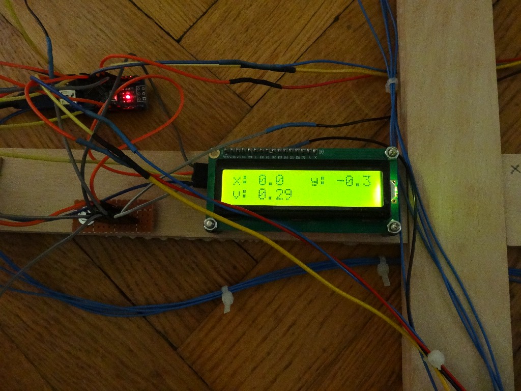
lcd.setCursor(2,0);
lcd.print(" ");
lcd.setCursor(10,0);
lcd.print(" ");
lcd.setCursor(3,1);
lcd.print(" ");
lcd.setCursor(2,0);
lcd.print(v_x,1);
lcd.setCursor(10,0);
lcd.print(v_y,1);
lcd.setCursor(3,1);
lcd.print(v_total,2);
delay(50);
}
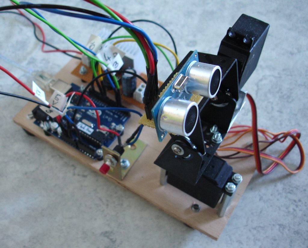
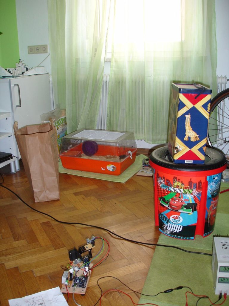
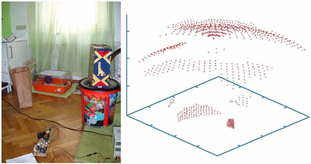
Projekt 3: 3D-Ultraschallscanner
Postiert man das Ultraschallmodul HC-SR04 auf einer schwenkbaren Servo-Montierung, so kann man die Entfernung d in einer bestimmten Raumrichtung (Winkel phi und teta) bestimmen. Dies liefert für viele verschiedene Richtungen einen kompletten Raumscan, welcher sich dann 2-dimensional etwa mit der Software gnuplot darstellen lässt.

Arduino-Code:
// =========================================================================
// ====== Programm zur Erstellung eines 3D-Scans mittels Ultraschall =======
// =========================================================================


#include <Servo.h>           // Inkludiert die Servodateien
#include <i2cmaster.h>       // Inkludiert die i2c-Bus-Dateien

#define TRIGPIN 3            // Pin to send trigger pulse
#define ECHOPIN 4            // Pin to receive echo pulse


Servo servo_horiz;           // Definiert den horizontalen servo
Servo servo_verti;           // Definiert den vertikalen servo
int taste;                   // Tastaturpin für Start des Scans
int winkel_horiz;            // horizontaler Winkel
int winkel_verti;            // vertikaler Winkel
int horiz_start = 120;        // horizontaler Startwinkel
int verti_start = 70;        // vertikaler Startwinkel
int schritte = 30;           // horizontale bzw. vertikale Schritte
int schrittweite = 3;        // Schrittweite der Servos

int distance = 0;            // Distanz in cm


// ************************************
// ************** SETUP ***************
// ************************************

void setup()
   {
    Serial.begin(9600);

    servo_horiz.attach(9);    // Set horizontalen servo to digital pin 9
    servo_verti.attach(10);   // Set vertikalen servo to digital pin 10

    pinMode(13, OUTPUT);
    pinMode(ECHOPIN, INPUT);
    pinMode(TRIGPIN, OUTPUT);
   }


// ********************************************
// ************** HAUPTSCHLEIFE ***************
// ********************************************

void loop()
   {

    taste = analogRead(A0);      // Abfrage, ob die Taste gedrückt wird und der Scan gestartet werden kann

    servo_horiz.write(horiz_start);
    servo_verti.write(verti_start);

    if (taste > 500)
       {
        // ********** Messung gestartet ************


        digitalWrite(13, HIGH);   // set the LED on
        delay(1000);              // wait for a second
        digitalWrite(13, LOW);    // set the LED off


        for (int i = 0; i <= schritte; i++)
          {
           servo_horiz.write(horiz_start);

           winkel_verti = verti_start + i * schrittweite;

           servo_verti.write(winkel_verti);

           delay(250);

           for (int j = 0; j <= schritte; j++)
              {
               winkel_horiz = horiz_start - j * schrittweite;

               servo_horiz.write(winkel_horiz);


               delay(500);

               digitalWrite(TRIGPIN, LOW);           // Set the trigger pin to low for 2 µS
               delayMicroseconds(2);

               digitalWrite(TRIGPIN, HIGH);          // Send a 10 µS high to trigger ranging
               delayMicroseconds(10);

               digitalWrite(TRIGPIN, LOW);           // Send pin low again

               distance = pulseIn(ECHOPIN, HIGH);    // Read in times pulse

               distance= distance / 58;              // Umrechnung der doppelten Laufzeit in µsek auf die Distanz bei einer Geschwindigkeit von 33 000 cm/sek


               Serial.print(schritte * schrittweite - j * schrittweite);
               Serial.print(" ");
               Serial.print(winkel_verti - 70);
               Serial.print(" ");
               Serial.println(distance);

              }
          }

        // ********** Messung beendet ************

        digitalWrite(13, HIGH);   // set the LED on
        delay(1000);              // wait for a second
        digitalWrite(13, LOW);    // set the LED off

        servo_horiz.write(horiz_start);
        servo_verti.write(verti_start);
       }

   }
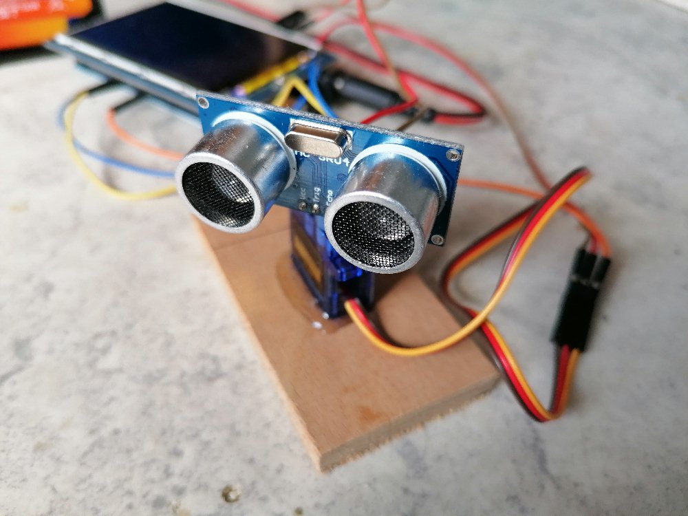
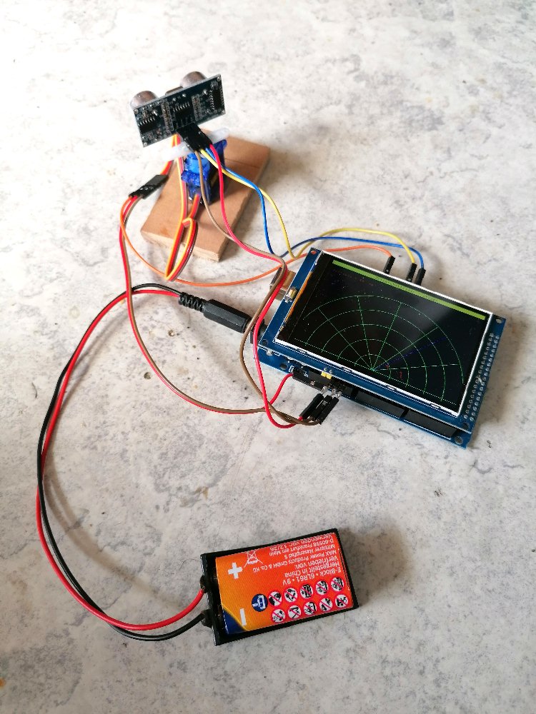
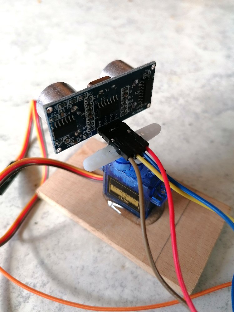
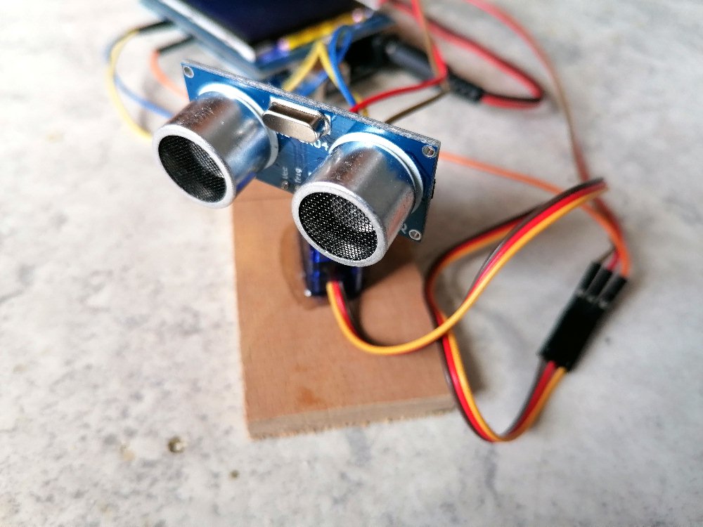
Projekt 4: Ultraschallradar
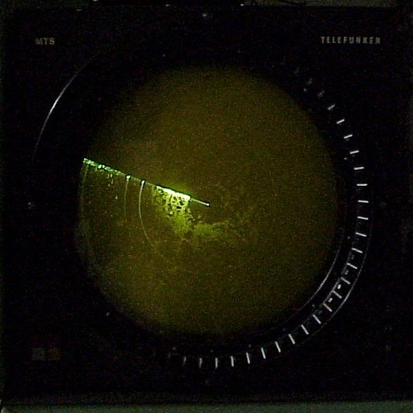
PPI-Scope der Firma Telefunken aus dem Jahre 1980
Bildquelle: https://de.wikipedia.org/wiki/Radarsichtger%C3%A4t#/media/Datei:PPI-scope.jpg, CC BY-SA 3.0
Wer kennt nicht die Radarbilder in Filmen, wo der Feind plötzlich in Form von Punkten auf dem Radarschirm bedrohlich auftaucht. In diesem Projekt bastel ich ein Radar, welches den Abstand zu Hindernissen in Abhängigkeit vom Positionswinkel darstellt.
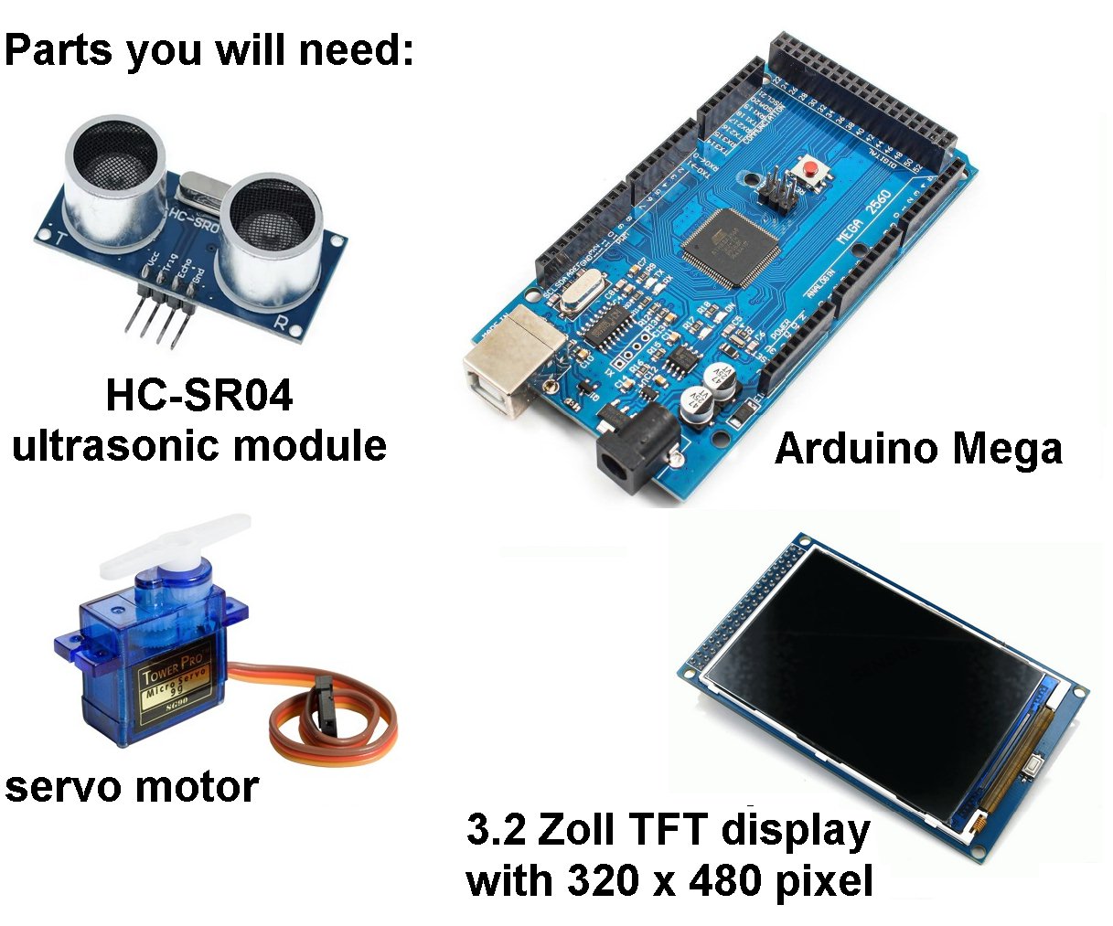
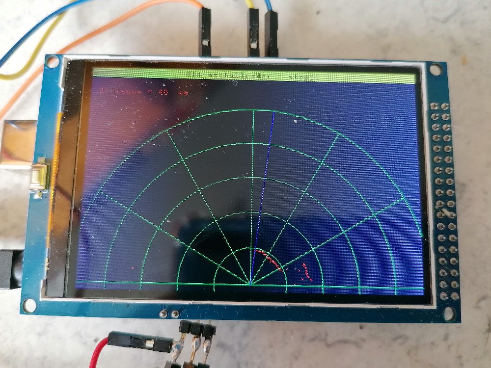
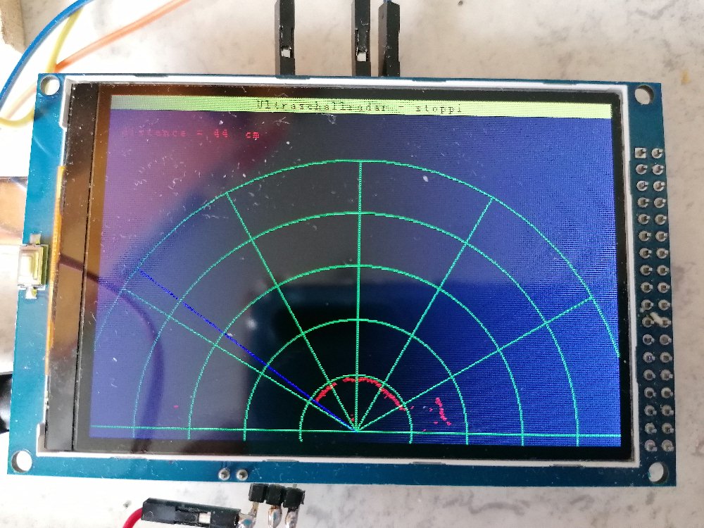
Dazu schwenke ich das Ultraschallmodul HC-SR04 mittels eines Servos von rechts nach links und wieder zurück. Auf dem Bildschirm bewegt sich der blaue Abtaststrahl entsprechend auch von rechts nach links und zurück. Die jeweilige Distanz der Hindernisse wird als roter Punkt auf dem Radarschirm angezeigt. Zusätzlich habe ich ein grünes Koordinatennetz mit Polarkoordinaten r und φ auf dem Bildschirm umgesetzt.
Der Arduino-Code:
#include <UTFT.h>
#include <Servo.h>

Servo myservo;              // Servoausgang

#define TRIGPIN 3                            // Pin to send trigger pulse
#define ECHOPIN 4                            // Pin to receive echo pulse


// Declare which fonts we will be using
extern uint8_t SmallFont[];

UTFT myGLCD(ILI9486,38,39,40,41);

int x_old, y_old, x_new, y_new;
int phi_Strahl, r_Strahl;           // r,phi des Radarstrahls
int x_Strahl_Ende, y_Strahl_Ende;   // Koordinaten des Strahlendes, Ausgangspunkt = (240, 310)
int distance;                       // Distanz des Objekts


// ***************************************
// **************** SETUP ****************
// ***************************************

void setup()
   {
    Serial.begin(9600);                          // Init serial interface

    // Setup the LCD
    myGLCD.InitLCD();
    myGLCD.setFont(SmallFont);
    myGLCD.clrScr();

    r_Strahl = 250;     // Länge des Radarstrahls

    myservo.attach(9);    // Set servo to digital pin 9

    pinMode(ECHOPIN, INPUT);
    pinMode(TRIGPIN, OUTPUT);
   }


// *******************************************
// ************** HAUPTSCHLEIFE **************
// *******************************************

void loop()
   {
    myGLCD.clrScr();
    myGLCD.setColor(255, 255, 0);
    myGLCD.fillRect(0, 0, 479, 13);
    myGLCD.setColor(0, 0, 0);
    myGLCD.setBackColor(255, 255, 0);
    myGLCD.print("Ultraschallradar - stoppi", CENTER, 1);

    myGLCD.setColor(255, 0, 0);
    myGLCD.setBackColor(0, 0, 0);
    myGLCD.print("distance = ", 12, 30);


    for (phi_Strahl = 0; phi_Strahl <= 180; phi_Strahl++)
       {
        x_Strahl_Ende = r_Strahl * cos(phi_Strahl * 3.141592654 / 180);
        y_Strahl_Ende = r_Strahl * sin(phi_Strahl * 3.141592654 / 180);

        myGLCD.setColor(0, 0, 255);
        myGLCD.drawLine(240,310,240 + x_Strahl_Ende, 310 - y_Strahl_Ende);


        myGLCD.setColor(0, 255, 0);
        myGLCD.drawCircle(240,310,50);
        myGLCD.drawCircle(240,310,100);
        myGLCD.drawCircle(240,310,150);
        myGLCD.drawCircle(240,310,200);

        //myGLCD.drawCircle(240,310,250);

        x_old = 240 + 250;
        y_old = 310 - 0;

        for (double i = 0; i <=  180; i++)
           {
            x_new = 240 + 250 * cos(i * 3.141592654 / 180);
            y_new = 310 - 250 * sin(i * 3.141592654 / 180);

            myGLCD.setColor(0,255,0);
            myGLCD.drawLine(x_old,y_old,x_new, y_new);

            x_old = x_new;
            y_old = y_new;
           }


        myGLCD.drawLine(240,310,480,310);
        myGLCD.drawLine(240,310,240 + 250 * cos(30 * 3.141592654 / 180), 310 - 250 * sin(30 * 3.141592654 / 180));
        myGLCD.drawLine(240,310,240 + 250 * cos(60 * 3.141592654 / 180), 310 - 250 * sin(60 * 3.141592654 / 180));
        myGLCD.drawLine(240,310,240, 310 - 250 * sin(90 * 3.141592654 / 180));
        myGLCD.drawLine(240,310,240 + 250 * cos(120 * 3.141592654 / 180), 310 - 250 * sin(120 * 3.141592654 / 180));
        myGLCD.drawLine(240,310,240 + 250 * cos(150 * 3.141592654 / 180), 310 - 250 * sin(150 * 3.141592654 / 180));
        myGLCD.drawLine(240,310,0,310);


        myservo.write(phi_Strahl);


        digitalWrite(TRIGPIN, LOW);                // Set the trigger pin to low for 2uS
        delayMicroseconds(2);
        digitalWrite(TRIGPIN, HIGH);               // Send a 10uS high to trigger ranging
        delayMicroseconds(10);
        digitalWrite(TRIGPIN, LOW);                // Send pin low again
        distance = pulseIn(ECHOPIN, HIGH);         // Read in times pulse
        distance = distance/58;                    // Calculate distance from time of pulse


        myGLCD.setColor(0,0,0);
        myGLCD.fillRect(90,30,130,40);
        myGLCD.setColor(255, 0, 0);
        myGLCD.printNumI(distance, 100,30);
        myGLCD.print("cm", 130, 30);

        //Serial.println(distance);

        delay(10);

        myGLCD.setColor(0, 0, 0);
        myGLCD.drawLine(240,310,240 + x_Strahl_Ende, 310 - y_Strahl_Ende);

        //distance = 125 + random(5);

        myGLCD.setColor(255, 0, 0);
        myGLCD.drawPixel(240 + distance * cos(phi_Strahl * 3.141592654 / 180), 310 - distance * sin(phi_Strahl * 3.141592654 / 180));
        myGLCD.drawCircle(240 + distance * cos(phi_Strahl * 3.141592654 / 180), 310 - distance * sin(phi_Strahl * 3.141592654 / 180),1);

       }

    // =======================================================================================================================================


    myGLCD.clrScr();
    myGLCD.setColor(255, 255, 0);
    myGLCD.fillRect(0, 0, 479, 13);
    myGLCD.setColor(0, 0, 0);
    myGLCD.setBackColor(255, 255, 0);
    myGLCD.print("Ultraschallradar - stoppi", CENTER, 1);

    myGLCD.setColor(255, 0, 0);
    myGLCD.setBackColor(0, 0, 0);
    myGLCD.print("distance = ", 12, 30);


    for (phi_Strahl = 180; phi_Strahl >= 0; phi_Strahl--)
       {
        x_Strahl_Ende = r_Strahl * cos(phi_Strahl * 3.141592654 / 180);
        y_Strahl_Ende = r_Strahl * sin(phi_Strahl * 3.141592654 / 180);

        myGLCD.setColor(0, 0, 255);
        myGLCD.drawLine(240,310,240 + x_Strahl_Ende, 310 - y_Strahl_Ende);


        myGLCD.setColor(0, 255, 0);
        myGLCD.drawCircle(240,310,50);
        myGLCD.drawCircle(240,310,100);
        myGLCD.drawCircle(240,310,150);
        myGLCD.drawCircle(240,310,200);

        //myGLCD.drawCircle(240,310,250);

        x_old = 240 + 250;
        y_old = 310 - 0;

        for (double i = 0; i <=  180; i++)
           {
            x_new = 240 + 250 * cos(i * 3.141592654 / 180);
            y_new = 310 - 250 * sin(i * 3.141592654 / 180);

            myGLCD.setColor(0,255,0);
            myGLCD.drawLine(x_old,y_old,x_new, y_new);

            x_old = x_new;
            y_old = y_new;
           }

        myGLCD.drawLine(240,310,480,310);
        myGLCD.drawLine(240,310,240 + 250 * cos(30 * 3.141592654 / 180), 310 - 250 * sin(30 * 3.141592654 / 180));
        myGLCD.drawLine(240,310,240 + 250 * cos(60 * 3.141592654 / 180), 310 - 250 * sin(60 * 3.141592654 / 180));
        myGLCD.drawLine(240,310,240, 310 - 250 * sin(90 * 3.141592654 / 180));
        myGLCD.drawLine(240,310,240 + 250 * cos(120 * 3.141592654 / 180), 310 - 250 * sin(120 * 3.141592654 / 180));
        myGLCD.drawLine(240,310,240 + 250 * cos(150 * 3.141592654 / 180), 310 - 250 * sin(150 * 3.141592654 / 180));
        myGLCD.drawLine(240,310,0,310);


        myservo.write(phi_Strahl);


        digitalWrite(TRIGPIN, LOW);                // Set the trigger pin to low for 2uS
        delayMicroseconds(2);
        digitalWrite(TRIGPIN, HIGH);               // Send a 10uS high to trigger ranging
        delayMicroseconds(10);
        digitalWrite(TRIGPIN, LOW);                // Send pin low again
        distance = pulseIn(ECHOPIN, HIGH);         // Read in times pulse
        distance = distance / 58;                  // Calculate distance from time of pulse


        myGLCD.setColor(0,0,0);
        myGLCD.fillRect(90,30,130,40);
        myGLCD.setColor(255, 0, 0);
        myGLCD.printNumI(distance, 100,30);
        myGLCD.print("cm", 130, 30);

        //Serial.println(distance);

        delay(10);

        myGLCD.setColor(0, 0, 0);
        myGLCD.drawLine(240,310,240 + x_Strahl_Ende, 310 - y_Strahl_Ende);

        //distance = 175 + random(5);

        myGLCD.setColor(255, 0, 0);
        myGLCD.drawPixel(240 + distance * cos(phi_Strahl * 3.141592654 / 180), 310 - distance * sin(phi_Strahl * 3.141592654 / 180));
        myGLCD.drawCircle(240 + distance * cos(phi_Strahl * 3.141592654 / 180), 310 - distance * sin(phi_Strahl * 3.141592654 / 180),1);

       }


   }
Für erste Messungen/Resultate musste meine Küche herhalten:
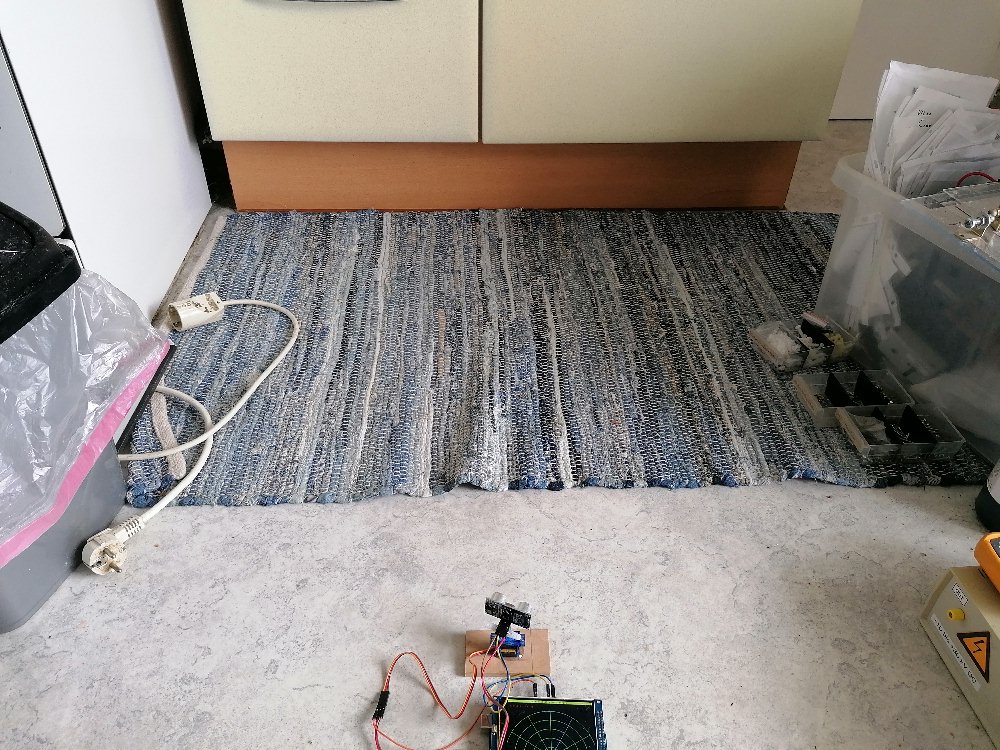
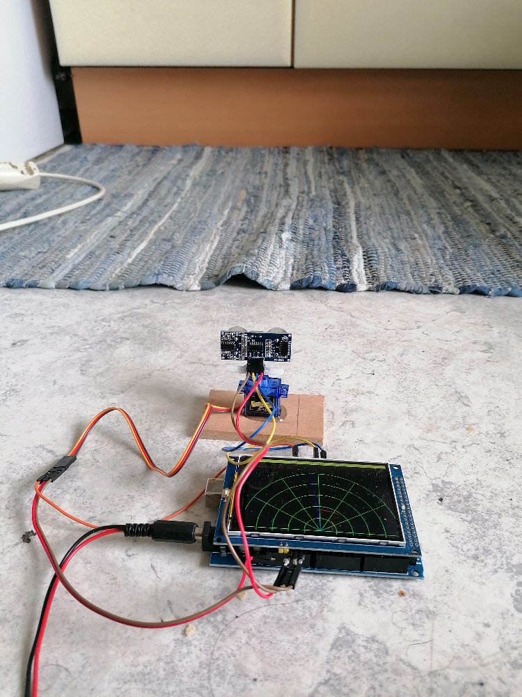
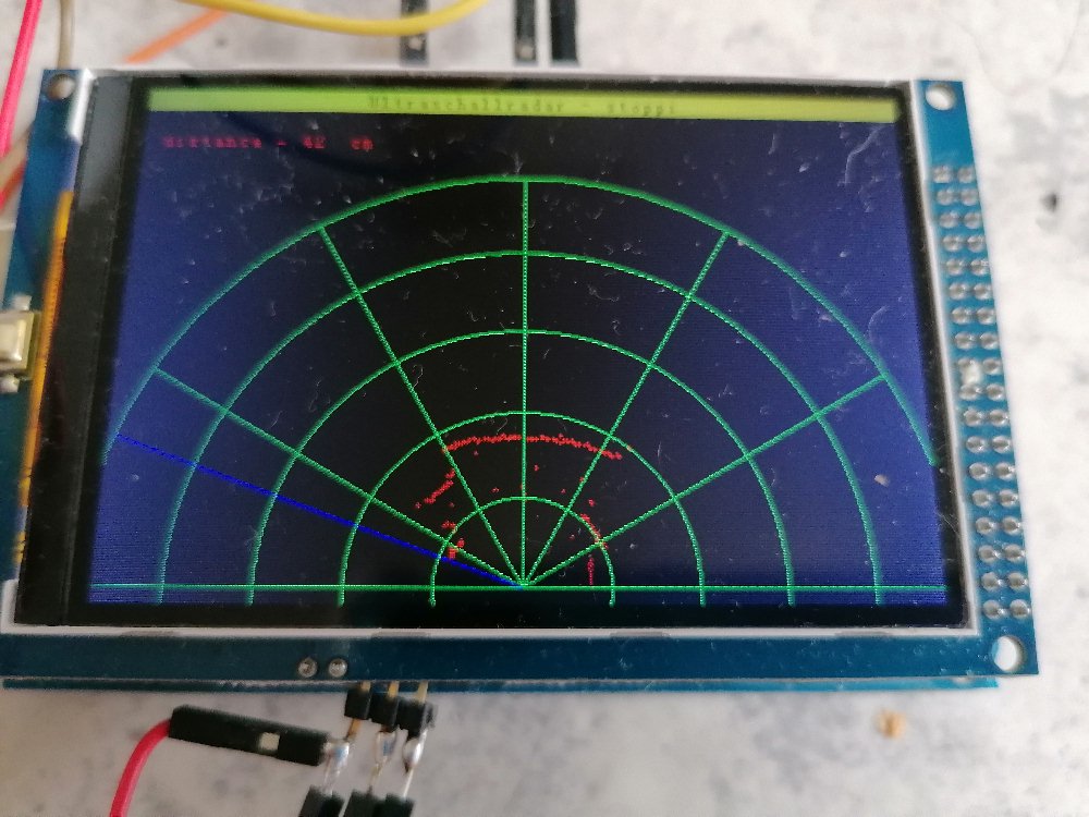
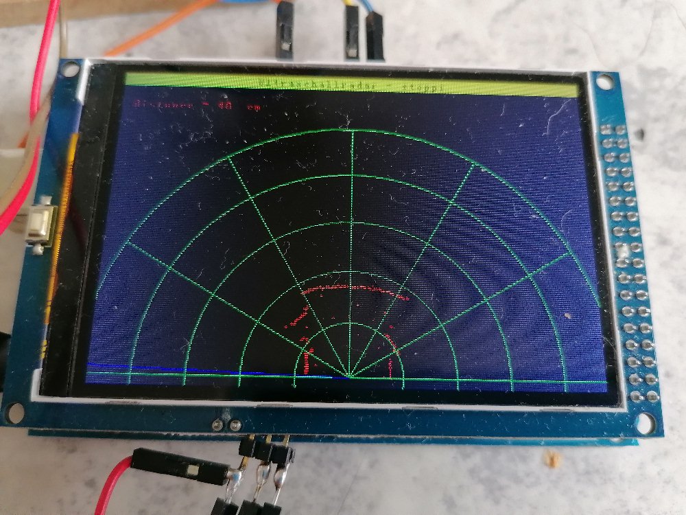

Mit den Ergebnissen bin ich eigentlich sehr zufrieden. Der Unterschrank der Einbauküche sowie der Mistkübel links und die Hindernisse rechts wurden ohne Probleme erkannt und auf dem Display dargestellt. Zum Abschluss noch das Youtube-Video: